(PRO) Directed level graphs
In this guide, we will see what we can do if we make the level graph directed and mark some doors as entrance-only or exit-only.
Note: All files from this example can be found at Examples/Grid2D/DirectedLevelGraphs.
Introduction
By default, all level graphs are undirected. That means that if you create a connection from Room 1 to Room 2 or from Room 2 to Room 1, the generator sees both cases to be equivalent. While this is fine for the majority of scenarios, it prevents us from doing some interesting things with the level design.
For example, imagine that you want to have a puzzle room where the player should enter the room on the left side and solve the puzzle, which, in turn, lets the player leave the room on the right side. With undirected graphs, this is impossible to achieve. Therefore, we have to introduce the notion of direction of individual connections in a level graph. When enabled, there appears a small arrow on each connection to indicate its direction. Moreover, each door can be marked as either entrance-only or exit-only, which gives us all the tools to implement the puzzle room.
Note: As with other features that limit the freedom of the generator, overuse of this feature can significantly decrease the performance. Always aim to have enough room templates and door positions to choose from.
Setup
Make the level graph directed
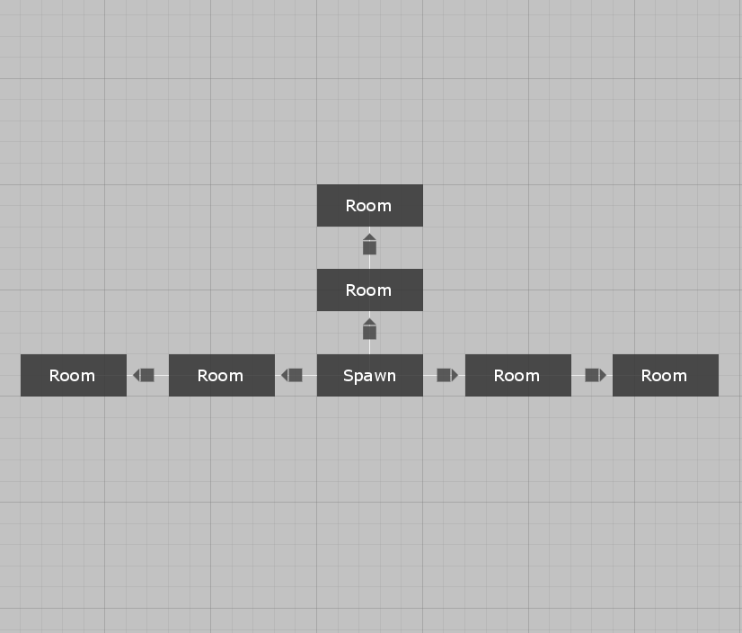
The first step in the setup is to make the level graph directed. To do that, you have to enable the Is Directed checkbox in the level graph inspector. After the level graph window is repainted (you might zoom in and out in the graph editor), you should see an arrow on each connection.
Add some entrances and exits
Making the level graph directed alone does not change anything in the way levels are generated. The next necessary step is to mark some doors as entrances or exits. This can be done only with the manual door mode. If a door is marked as an exit, it can be used only for connections that are directed away from the room. Likewise, if a door is marked as an entrance, it can be used only for connections that are directed towards the room.
Example
Note: All files from this example can be found at Edgar/Examples/DirectedLevelGraphs.
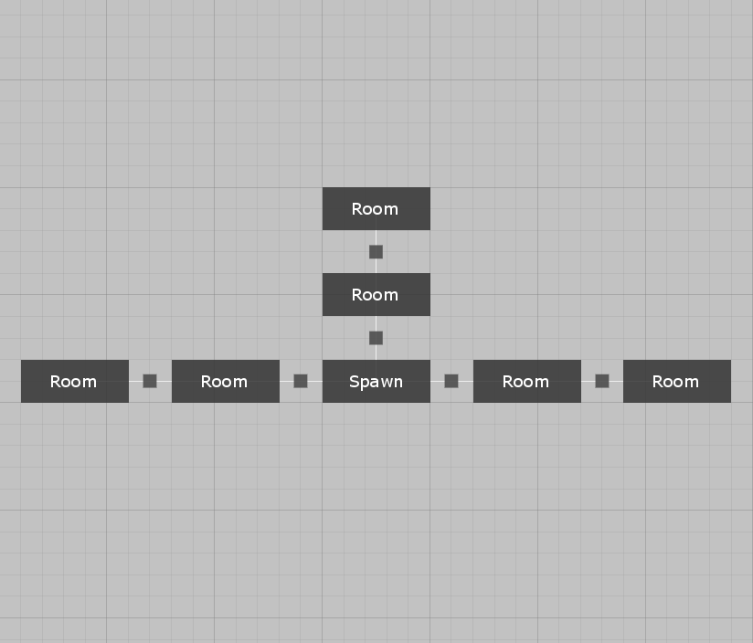
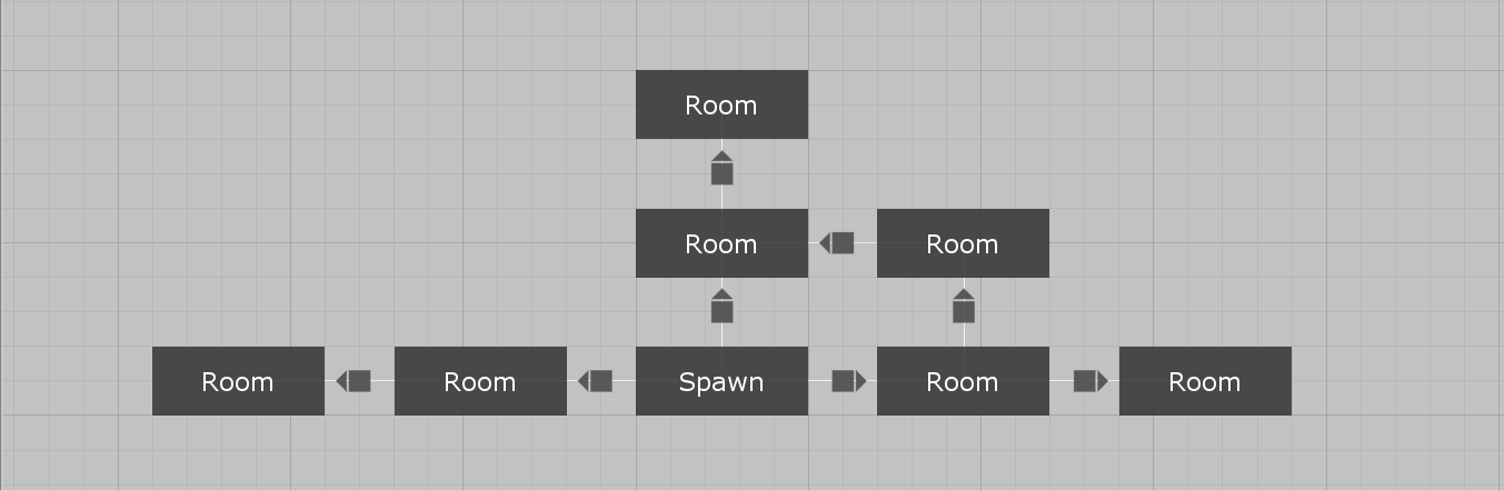
Level graph
First, I created a simple directed level graph that can be seen below. The graph is pretty simple. All connections are directed away from the spawn room and there is also a single cycle.
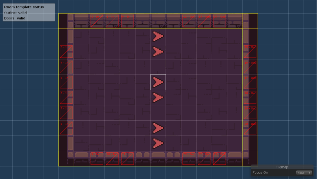
Room templates
Next, I created a room template that should illustrate how we could approach puzzle rooms as described above. All the doors on the left side are marked as entrances and all the doors on the right side are marked as exits. That means that the player will always enter the room from the left side and exit on the right side. I also created a mirrored version of the room template.
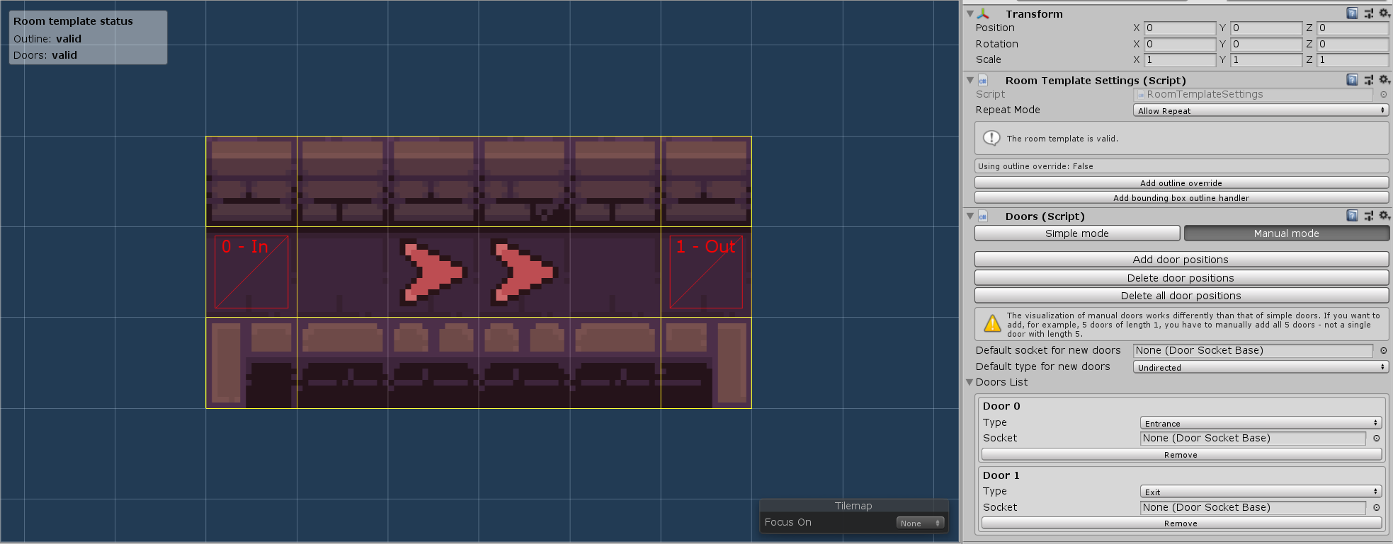
Corridor room templates
I also created directed versions of both vertical and horizontal corridors. This step is completely optional - if you do not care about the direction of corridors, you can use the default undirected doors.

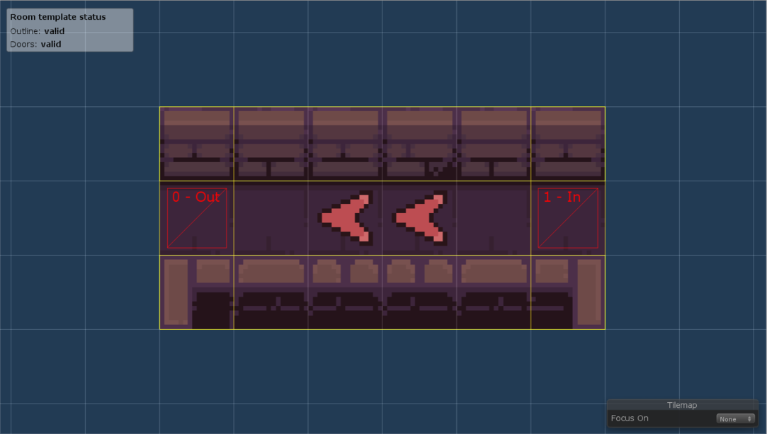
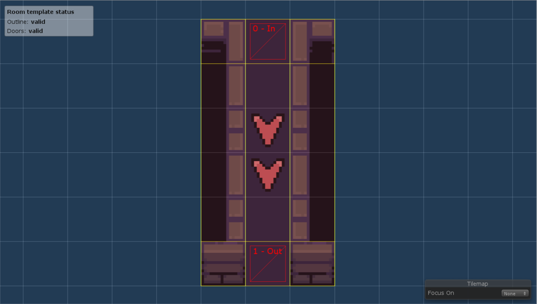
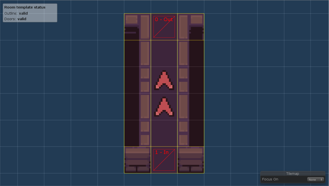
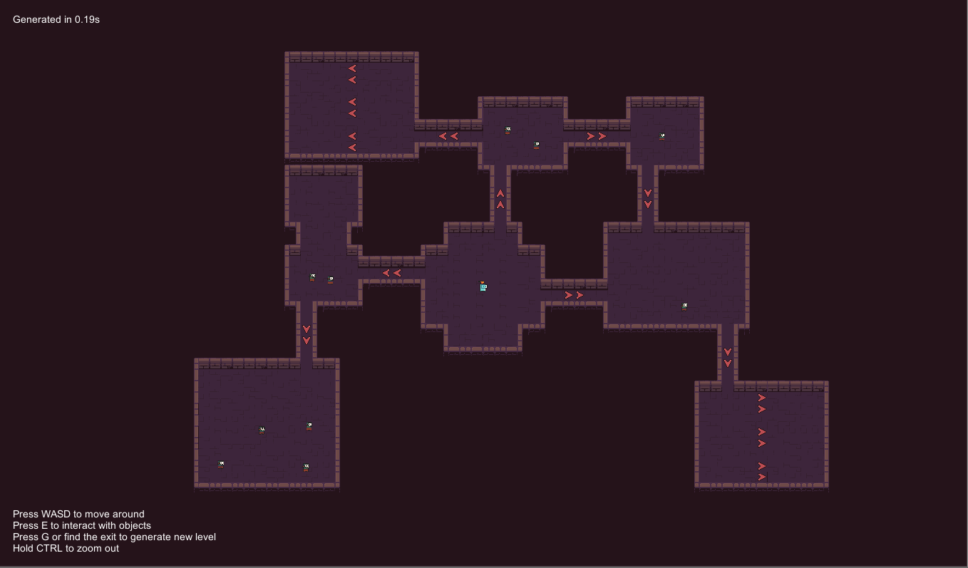
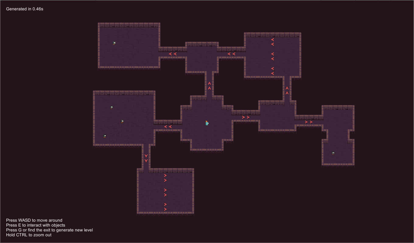
Note: The arrow tiles are placed on the room templates manually to better illustrate the direction of the corridors.
Results